The RO membrane working principle sounds simple. Apply enough pressure, and water crosses a semi-permeable membrane while dissolved solids stay behind. In practice, separation depends on osmotic pressure, membrane chemistry, and molecular transport physics. This guide explains each layer of that science for engineers, plant operators, and maintenance teams.
Reverse osmosis (RO) is the finest pressure-driven barrier in the membrane spectrum. It rejects 95–99.5% of dissolved salts through a dense polyamide layer. Its effective pore size sits near 0.0001 µm (0.1 nm). The global RO membrane market reached USD 6.8 billion in 2024. Analysts project USD 12.4 billion by 2034, a CAGR of 6.2%, driven by desalination and ultrapure water. Engineers who master this RO membrane working principle set correct pressures, design better pretreatment, and diagnose flux loss faster.
For a system-level tour of RO hardware, applications, and maintenance, read How Does RO Membrane Work?.
*Last Updated: September 2026 | Industry-Verified Technical Data
Fundamental RO Membrane Working Principle
A reverse osmosis membrane is a semi-permeable barrier. It allows solvent molecules, meaning water, to pass through while rejecting dissolved solutes such as salts, minerals, and organic compounds. Three key factors govern the RO membrane working principle: applied pressure, the semi-permeable skin, and the concentration gradient across it.
| Factor | Role in Separation | Typical Value |
| Applied pressure | Exceeds feed osmotic pressure and forces water through the membrane against the natural osmotic gradient | Brackish RO: 100–450 psi (7–31 bar); seawater RO: 800–1,200 psi (55–83 bar) |
| Semi-permeable membrane | Thin-film composite (TFC) polyamide layer that passes water while rejecting 95–99.5% of dissolved salts | Effective pore size near 0.0001 µm (0.1 nm); effectively non-porous to dissolved ions |
| Concentration gradient | The solute difference across the membrane creates the osmotic pressure that applied pressure must overcome | Osmotic pressure near 11 psi (0.75 bar) per 1,000 mg/L TDS |
During operation, feed water flows across the membrane surface under pressure. Applied pressure must exceed the feed’s osmotic pressure. That pressure runs about 11 psi (0.75 bar) per 1,000 mg/L of dissolved solids. Brackish water at 2,000 mg/L TDS therefore needs at least 22 psi (1.5 bar) before permeate can form. Practical systems run 100–225 psi (7–15 bar) to reach adequate flux and recovery.
Every element rating and every pressure setting traces back to this same RO membrane working principle. Seawater duty pushes the requirement into the 800–1,200 psi (55–83 bar) class covered in our seawater desalination guide.
RO Membrane Working Principle: Osmosis and Reverse Osmosis Compared
Natural osmosis is a spontaneous, entropy-driven process. When a semi-permeable membrane separates two solutions of different concentration, water migrates from the low-TDS side to the high-TDS side. Flow continues until the pressure difference equals the osmotic pressure of the concentrated solution.
Reverse osmosis reverses that direction with external hydraulic pressure. Once applied pressure exceeds osmotic pressure, water flows from the high-concentration side to the low-concentration side. That direction is the opposite of natural osmosis. This RO membrane working principle produces purified permeate on the low-pressure side. The remaining feed concentrates into the reject stream.
| Parameter | Osmosis | Reverse Osmosis |
| Driving force | Concentration gradient (spontaneous) | Applied hydraulic pressure |
| Water flow direction | Low TDS → high TDS | High TDS → low TDS |
| Energy requirement | None (natural process) | High-pressure pump, 0.5–4 kWh/m³ depending on salinity |
| Result | Equalizes concentration | Separates pure water from dissolved solids |
The same physics places RO at the finest end of the pressure-driven spectrum. Our membrane separation principle guide compares RO with ultrafiltration and nanofiltration on this basis.
Structure of a Thin-Film Composite (TFC) RO Membrane
Modern RO membranes are thin-film composite (TFC) polyamide elements, typically spiral-wound. The TFC construction translates the RO membrane working principle into a manufacturable, high-flux barrier built from three layers.
| Layer | Typical Thickness | Function |
| Polyamide active layer | 0.1–0.2 µm | Ultra-thin cross-linked skin performing salt rejection; formed by interfacial polymerization; sets rejection, permeability, and chlorine tolerance |
| Polysulfone support layer | About 40 µm | Porous mechanical support for the fragile skin with minimal hydraulic resistance to permeate flow |
| Polyester backing fabric | About 120 µm | Non-woven fabric giving structural strength and routing permeate to the collection tube |
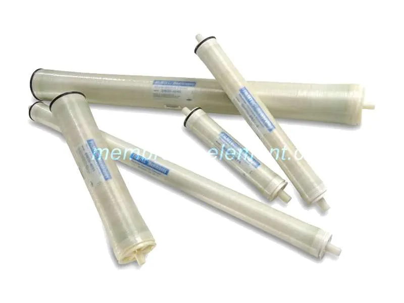
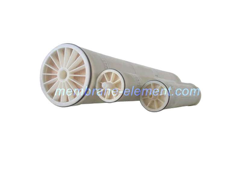
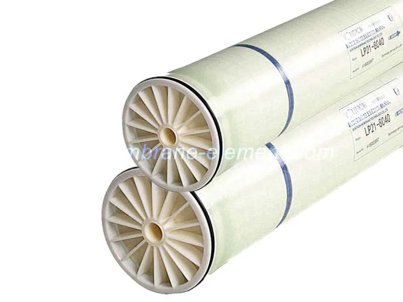
Manufacturers fold the membrane into leaves and wind them around a central permeate tube. Feed spacers separate the leaves to create flow channels. A standard 4-inch element contains about 7–8 m² of membrane area. An 8-inch element carries 30–40 m². For element formats and replacement options, see types of RO membrane elements.
The material properties that follow from this structure are detailed in our RO membrane characteristics guide. It covers desalination rate, pH tolerance, and chemical resistance.
Mass Transport Mechanisms in RO Membrane Separation
Two transport models describe how water and salt cross the membrane. The solution-diffusion model is the widely accepted one. Water adsorbs into the polyamide at the feed side. It then diffuses through the dense polymer under a chemical-potential gradient and desorbs at the permeate side. Salt follows the same path but diffuses far more slowly. Hydrated ions are large relative to the polymer free volume.
The pore-flow model offers an alternative picture. It assumes micro-pores near 0.5–1.0 nm in diameter. Water flows through them under hydraulic pressure while solutes are rejected by size. Real membranes combine both behaviors; the dense skin shows diffusive and convective transport at once.
| Parameter | Solution-Diffusion Model | Pore Flow Model |
| Water flux (J∞) | A(ΔP − Δπ) | K(ΔP − Δπ) |
| Solute flux (Jₚ) | B(Cₛ − Cₙ) | J∞ · Cₙ |
| Salt rejection | R = 1 − Cₙ/Cₛ | R = 1 − Cₙ/Cₛ |
| Physical picture | Dissolution and diffusion through polymer free volume | Pressure-driven flow through micro-pores |
Here A is the water permeability coefficient and B is the solute permeability coefficient. ΔP is the transmembrane pressure and Δπ is the osmotic pressure difference. Cₛ is feed concentration and Cₙ is permeate concentration.
These equations explain the RO membrane working principle at molecular scale. Field monitoring turns the rejection formula into practice. Our RO membrane separation technology guide and RO membrane evaluation indices guide show how.
Cross-Flow Separation and Concentration Polarization
RO elements run in cross-flow, not dead-end filtration. That geometry follows from the RO membrane working principle: rejected salts must be swept away before they accumulate. Feed flows parallel to the membrane surface, permeate exits perpendicular to it, and concentrate carries the salts away.
Concentration polarization still occurs. Rejected salts build up in a thin boundary layer at the membrane wall, pushing wall concentration above bulk concentration. Local osmotic pressure then rises and net driving pressure (ΔP − Δπ) falls. Severe polarization seeds the scaling and fouling documented in types of RO membrane fouling.
Designers control polarization with cross-flow velocity, feed spacers, flux moderation, and antiscalant dosing. Recovery limits belong to the design data in our RO membrane performance parameters guide.
Key Factors Affecting RO Membrane Performance
Flux and rejection obey the RO membrane working principle in the field, but five operating factors move the real numbers.
- Feed pressure. Water flux rises with net driving pressure (flux ∝ ΔP − Δπ). Higher pressure also raises specific energy consumption, so the optimum balances output against cost. Element pressure limits are listed in our RO membrane operating pressure guide.
- Feed temperature. Flux climbs about 2–3% per °C as viscosity falls and diffusion accelerates. Standard design references 25 °C and applies temperature correction factors at other temperatures.
- Feed TDS and osmotic pressure. Higher TDS raises osmotic pressure, shrinking net driving pressure and flux. Seawater RO therefore needs 800–1,200 psi (55–83 bar), while brackish RO runs far lower.
- Recovery rate. Recovery, the ratio of permeate flow to feed flow, concentrates the feed side. Single elements recover 8–15%; a 7-element pressure vessel reaches 50–75% overall. Higher recovery raises tail-element osmotic pressure and scaling risk.
- Membrane fouling. Suspended solids, organics, biological growth, and scale reduce effective membrane area and raise pressure drop. Clean when normalized flux falls 10–15% or pressure drop climbs 10–15%; our RO membrane cleaning frequency guide sets the schedule.
The RO Separation Process: From Element to Staged System
A single element splits feed water into two streams: permeate and concentrate. Six to eight elements share one pressure vessel, and the concentrate of each element becomes the feed of the next. Overall vessel recovery climbs to 50–75% while each element contributes only 8–15%.
Full plants stage the vessels into arrays. Brackish trains commonly recover 75–90%; seawater single passes recover 40–50% and lean on energy-recovery devices to cut pumping cost. Feed water quality governs the whole train, so start with our RO membrane feed water requirements guide.
Conclusion
The RO membrane working principle combines osmosis physics with an engineered barrier. Pressure overcomes osmotic pressure, and a three-layer TFC skin separates water from salt by solution-diffusion.
Operating factors then decide real-world flux, rejection, and element life. Xi’an CHIWATEC supplies RO membranes matched to your water analysis; send us feed data and target quality for element recommendations.
Contact our engineering team: [email protected], [email protected], or [email protected].
FAQ: Membrane Transport and Separation Process
Q1: What is net driving pressure in RO separation?
Net driving pressure equals applied pressure minus the osmotic pressure difference (ΔP − Δπ). Water flux follows J∞ = A(ΔP − Δπ). If applied pressure falls below osmotic pressure, permeate production stops. Flow would then reverse toward natural osmosis. Plants always run well above the osmotic minimum.
Q2: Is RO rejection a sieving or a diffusion process?
Mostly diffusion. TFC polyamide has no continuous pores; water and salt dissolve into the skin and diffuse through its free volume. Water diffuses quickly while hydrated ions diffuse slowly. Rejection therefore comes from solubility and diffusivity differences, not size sieving alone.
Q3: How much pressure does an RO membrane need?
The minimum equals feed osmotic pressure, about 11 psi per 1,000 mg/L TDS. Brackish systems operate at 100–450 psi in practice. Seawater at 35,000 mg/L carries an osmotic pressure near 390 psi (27 bar). That is why seawater systems need 800–1,200 psi (55–83 bar).
Q4: Why does higher recovery raise scaling risk?
Recovery concentrates the feed. At 75% recovery, the concentrate carries roughly four times the feed TDS. Osmotic pressure then climbs and sparingly soluble salts approach their solubility limits at the tail elements. Designers cap stage recovery and dose antiscalants to stay below those limits.
Q5: How does concentration polarization reduce flux?
Polarization raises salt concentration at the membrane wall above the bulk value. Local osmotic pressure rises and net driving pressure falls, so flux drops even when feed pressure stays constant. Cross-flow velocity, spacers, and flux moderation keep the effect small.
Related Resources
Recommended Membrane Technology Guides
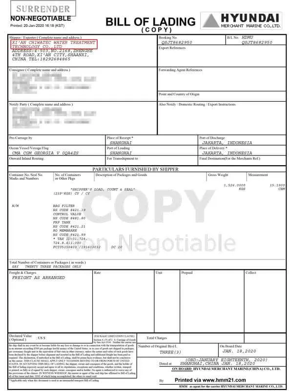
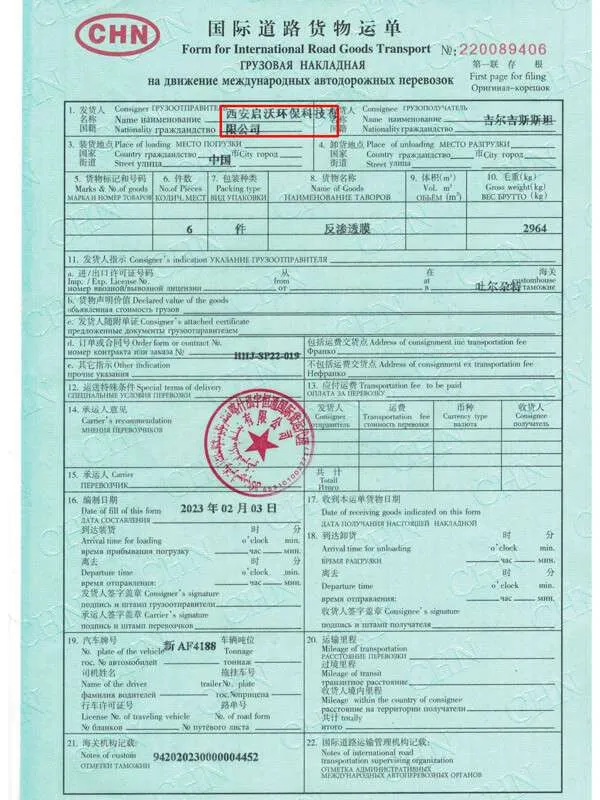
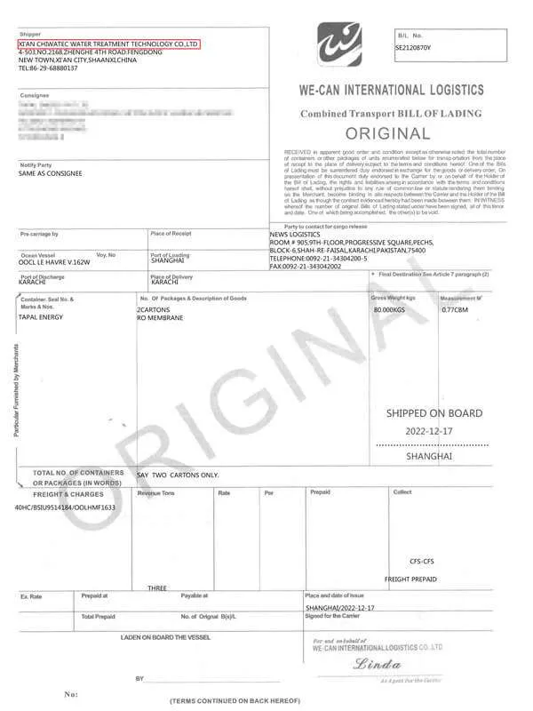
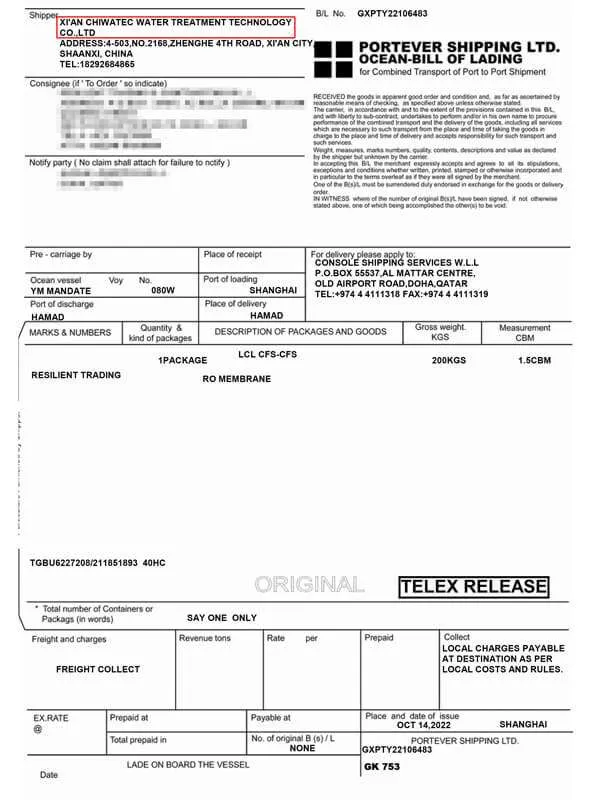
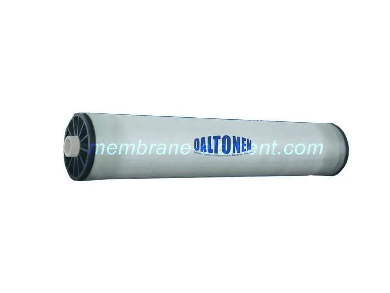
Xi’an CHIWATEC Water Treatment Technology provide the RO membrane to clients both inland and oversea with more than 10years experience. We manufacture our own brand Daltonen RO membrane and we are also the official distributor of Dupont, Toray, CSM, Nitto, LG and Vontron RO membrane. Whatever product you need, we cold meet your requirement.
Contact me for more info and best price.